Special-purpose diodes
Schottky diodesSchottky diodes are constructed of a metal-to-N junction rather than a P-N semiconductor junction. Also known as hot-carrier diodes, Schottky diodes are characterized by fast switching times (low reverse-recovery time), low forward voltage drop (typically 0.25 to 0.4 volts for a metal-silicon junction), and low junction capacitance. The schematic symbol for a Schottky diode is shown here:
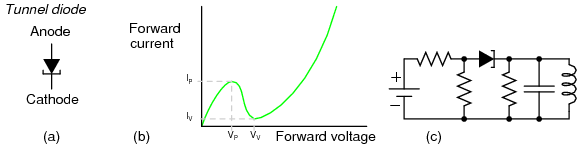
In terms of forward voltage drop (VF), reverse-recovery time (trr), and junction capacitance (CJ), Schottky diodes are closer to ideal than the average "rectifying" diode. This makes them well suited for high-frequency applications. Unfortunately, though, Schottky diodes typically have lower forward current (IF) and reverse voltage (VRRM and VDC) ratings than rectifying diodes and are thus unsuitable for applications involving substantial amounts of power. Schottky diode technology finds broad application in high-speed computer circuits, where the fast switching time equates to high speed capability, and the low forward voltage drop equates to less power dissipation when conducting. Tunnel diodesTunnel diodes exploit a strange quantum phenomenon called resonant tunneling to provide interesting forward-bias characteristics. When a small forward-bias voltage is applied across a tunnel diode, it begins to conduct current. As the voltage is increased, the current increases and reaches a peak value called the peak current (IP). If the voltage is increased a little more, the current actually begins to decrease until it reaches a low point called the valley current (IV). If the voltage is increased further yet, the current begins to increase again, this time without decreasing into another "valley." Both the schematic symbol and a current/voltage plot for the tunnel diode are shown in the following illustration:
The forward voltages necessary to drive a tunnel diode to its peak and valley currents are known as peak voltage (VP) and valley voltage (VV), respectively. The region on the graph where current is decreasing while applied voltage is increasing (between VP and VV on the horizontal scale) is known as the region of negative resistance. Tunnel diodes, also known as Esaki diodes in honor of their Japanese inventor Leo Esaki, are able to transition between peak and valley current levels very quickly, "switching" between high and low states of conduction much faster than even Schottky diodes. Tunnel diode characteristics are also relatively unaffected by changes in temperature. Unfortunately, tunnel diodes are not good rectifiers, as they have relatively high "leakage" current when reverse-biased. Consequently, they find application only in special circuits where their unique tunnel effect has value. In order to exploit the tunnel effect, these diodes are maintained at a bias voltage somewhere between the peak and valley voltage levels, always in a forward-biased polarity (anode positive, and cathode negative). Perhaps the most common application of a tunnel diode is in simple high-frequency oscillator circuits, where they allow a DC voltage source to contribute power to an LC "tank" circuit, the diode conducting when the voltage across it reaches the peak (tunnel) level and effectively insulating at all other voltages. Light-emitting diodesDiodes, like all semiconductor devices, are governed by the principles described in quantum physics. One of these principles is the emission of specific-frequency radiant energy whenever electrons fall from a higher energy level to a lower energy level. This is the same principle at work in a neon lamp, the characteristic pink-orange glow of ionized neon due to the specific energy transitions of its electrons in the midst of an electric current. The unique color of a neon lamp's glow is due to the fact that it's neon gas inside the tube, and not due to the particular amount of current through the tube or voltage between the two electrodes. Neon gas glows pinkish-orange over a wide range of ionizing voltages and currents. Each chemical element has its own "signature" emission of radiant energy when its electrons "jump" between different, quantized energy levels. Hydrogen gas, for example, glows red when ionized; mercury vapor glows blue. This is what makes spectrographic identification of elements possible. Electrons flowing through a PN junction experience similar transitions in energy level, and emit radiant energy as they do so. The frequency of this radiant energy is determined by the crystal structure of the semiconductor material, and the elements comprising it. Some semiconductor junctions, composed of special chemical combinations, emit radiant energy within the spectrum of visible light as the electrons transition in energy levels. Simply put, these junctions glow when forward biased. A diode intentionally designed to glow like a lamp is called a light-emitting diode, or LED. Diodes made from a combination of the elements gallium, arsenic, and phosphorus (called gallium-arsenide-phosphide) glow bright red, and are some of the most common LEDs manufactured. By altering the chemical constituency of the PN junction, different colors may be obtained. Some of the currently available colors other than red are green, blue, and infra-red (invisible light at a frequency lower than red). Other colors may be obtained by combining two or more primary-color (red, green, and blue) LEDs together in the same package, sharing the same optical lens. For instance, a yellow LED may be made by merging a red LED with a green LED. The schematic symbol for an LED is a regular diode shape inside of a circle, with two small arrows pointing away (indicating emitted light):
This notation of having two small arrows pointing away from the device is common to the schematic symbols of all light-emitting semiconductor devices. Conversely, if a device is light-activated (meaning that incoming light stimulates it), then the symbol will have two small arrows pointing toward it. It is interesting to note, though, that LEDs are capable of acting as light-sensing devices: they will generate a small voltage when exposed to light, much like a solar cell on a small scale. This property can be gainfully applied in a variety of light-sensing circuits. Because LEDs are made of different chemical substances than normal rectifying diodes, their forward voltage drops will be different. Typically, LEDs have much larger forward voltage drops than rectifying diodes, anywhere from about 1.6 volts to over 3 volts, depending on the color. Typical operating current for a standard-sized LED is around 20 mA. When operating an LED from a DC voltage source greater than the LED's forward voltage, a series-connected "dropping" resistor must be included to prevent full source voltage from damaging the LED. Consider this example circuit:
With the LED dropping 1.6 volts, there will be 4.4 volts dropped across the resistor. Sizing the resistor for an LED current of 20 mA is as simple as taking its voltage drop (4.4 volts) and dividing by circuit current (20 mA), in accordance with Ohm's Law (R=E/I). This gives us a figure of 220 Ω. Calculating power dissipation for this resistor, we take its voltage drop and multiply by its current (P=IE), and end up with 88 mW, well within the rating of a 1/8 watt resistor. Higher battery voltages will require larger-value dropping resistors, and possibly higher-power rating resistors as well. Consider this example for a supply voltage of 24 volts:
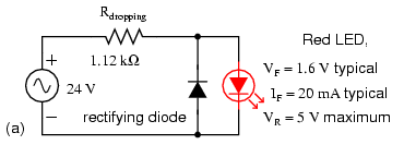
Here, the dropping resistor must be increased to a size of 1.12 kΩ in order to drop 22.4 volts at 20 mA so that the LED still receives only 1.6 volts. This also makes for a higher resistor power dissipation: 448 mW, nearly one-half a watt of power! Obviously, a resistor rated for 1/8 watt power dissipation or even 1/4 watt dissipation will overheat if used here. Dropping resistor values need not be precise for LED circuits. Suppose we were to use a 1 kΩ resistor instead of a 1.12 kΩ resistor in the circuit shown above. The result would be a slightly greater circuit current and LED voltage drop, resulting in a brighter light from the LED and slightly reduced service life. A dropping resistor with too much resistance (say, 1.5 kΩ instead of 1.12 kΩ) will result in less circuit current, less LED voltage, and a dimmer light. LEDs are quite tolerant of variation in applied power, so you need not strive for perfection in sizing the dropping resistor. Also because of their unique chemical makeup, LEDs have much, much lower peak-inverse voltage (PIV) ratings than ordinary rectifying diodes. A typical LED might only be rated at 5 volts in reverse-bias mode. Therefore, when using alternating current to power an LED, you should connect a protective rectifying diode in series with the LED to prevent reverse breakdown every other half-cycle:
As lamps, LEDs are superior to incandescent bulbs in many ways. First and foremost is efficiency: LEDs output far more light power per watt than an incandescent lamp. This is a significant advantage if the circuit in question is battery-powered, efficiency translating to longer battery life. Second is the fact that LEDs are far more reliable, having a much greater service life than an incandescent lamp. This advantage is primarily due to the fact that LEDs are "cold" devices: they operate at much cooler temperatures than an incandescent lamp with a white-hot metal filament, susceptible to breakage from mechanical and thermal shock. Third is the high speed at which LEDs may be turned on and off. This advantage is also due to the "cold" operation of LEDs: they don't have to overcome thermal inertia in transitioning from off to on or vice versa. For this reason, LEDs are used to transmit digital (on/off) information as pulses of light, conducted in empty space or through fiber-optic cable, at very high rates of speed (millions of pulses per second). One major disadvantage of using LEDs as sources of illumination is their monochromatic (single-color) emission. No one wants to read a book under the light of a red, green, or blue LED. However, if used in combination, LED colors may be mixed for a more broad-spectrum glow. Laser diodesThe laser diode is a further development upon the regular light-emitting diode, or LED. The term "laser" itself is actually an acronym, despite the fact it's often written in lower-case letters. "Laser" stands for Light Amplification by Stimulated Emission of Radiation, and refers to another strange quantum process whereby characteristic light emitted by electrons transitioning from high-level to low-level energy states in a material stimulate other electrons in a substance to make similar "jumps," the result being a synchronized output of light from the material. This synchronization extends to the actual phase of the emitted light, so that all light waves emitted from a "lasing" material are not just the same frequency (color), but also the same phase as each other, so that they reinforce one another and are able to travel in a very tightly-confined, nondispersing beam. This is why laser light stays so remarkably focused over long distances: each and every light wave coming from the laser is in step with each other:
Incandescent lamps produce "white" (mixed-frequency, or mixed-color) light. Regular LEDs produce monochromatic light: same frequency (color), but different phases, resulting in similar beam dispersion. Laser LEDs produce coherent light: light that is both monochromatic (single-color) and monophasic (single-phase), resulting in precise beam confinement. Laser light finds wide application in the modern world: everything from surveying, where a straight and nondispersing light beam is very useful for precise sighting of measurement markers, to the reading and writing of optical disks, where only the narrowness of a focused laser beam is able to resolve the microscopic "pits" in the disk's surface comprising the binary 1's and 0's of digital information. Some laser diodes require special high-power "pulsing" circuits to deliver large quantities of voltage and current in short bursts. Other laser diodes may be operated continuously at lower power. In the latter case, laser action occurs only within a certain range of diode current, necessitating some form of current-regulator circuit. As laser diodes age, their power requirements may change (more current required for less output power), but it should be remembered that low-power laser diodes, like LEDs, are fairly long-lived devices, with typical service lives in the tens of thousands of hours. PhotodiodesVaractor diodesConstant-current diodesA constant-current diode, also known as a current-limiting diode, or current-regulating diode, does exactly what its name implies: it regulates current through it to some maximum level. If you try to force more current through a constant-current diode than its current-regulation point, it simply "fights back" by dropping more voltage. If we were to build the following circuit and plot diode current over diode current, we'd get a graph that rises normally at first and then levels off at the current regulation point:
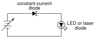
One interesting application for a constant-current diode is to automatically limit current through an LED or laser diode over a wide range of power supply voltages, like this:
Of course, the constant-current diode's regulation point should be chosen to match the LED or laser diode's optimum forward current. This is especially important for the laser diode, not so much for the LED, as regular LEDs tend to be more tolerant of forward current variations. Another application is in the charging of small secondary-cell batteries, where a constant charging current leads to very predictable charging times. Of course, large secondary-cell battery banks might also benefit from constant-current charging, but constant-current diodes tend to be very small devices, limited to regulating currents in the milliamp range. www.allaboutcircuits.com |


 سالها دل طلب جام جم از ما میکرد، آنچه خود داشت ز بیگانه تمنا میکرد